
Wiki
Overview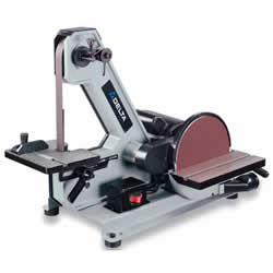
| Name: Delta Sander |
| Location: Metal Shop |
| Status: Operational |
| Training: Required |
| Slack Channel: #Help-Metalworking |
| Owner: denhac |
Training
This machine requires completion of the Metal Shop Safety Our calendar of trainings can be found Here
Operation
Safety
NEVER TURN THE MACHINE “ON” with the work-piece contacting the abrasive surface. Kickback can occur.
CLEAN THE MACHINE and dust collector thoroughly when processing different types of workpieces steel, or aluminum). Combining wood and metal dust can create an explosion or fire hazard.
DO NOT SAND OR POLISH MAGNESIUM. Fire will result.
PREVENT THE WORKPIECE from contacting the sanding belt before starting the tool. Loss of control of the workpiece is dangerous.
AVOID AWKWARD OPERATIONS AND HAND POSITIONS. A sudden slip could cause a hand to move into the abrasive disc or belt. MAINTAIN A MAXIMUM CLEARANCE OF 1/16″ between the table and the abrasive disc. The workpiece could be drawn into the space between the abrasive disc and the table.
SUPPORT THE WORKPIECE firmly with a miter gauge, backstop, or work table Loss of control of the workpiece can result in injury.
AVOID KICKBACK by sanding in accordance with the directional arrows. Feed the workpiece against the downward rotation side of the disc or the forward rotation of the belt. Loss of control of the workpiece can result in injury.
DO NOT SAND very small or very thin workpieces that cannot be safely controlled. Loss of control of the workpiece can result in injury.
PROPERLY SUPPORT LONG OR WIDE WORKPIECES. Loss of control of the workpiece is dangerous.
NEVER PERFORM LAYOUT, ASSEMBLY, OR SET-UP WORK on the table/work area when the machine is running. A sudden slip could cause a hand to move into the abrasive surface. Severe injury can result.
Setup
TRACKING THE SANDING BELT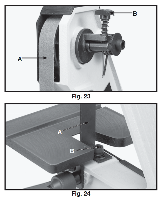 The belt tracking adjustment is set at the factory so that the belt (A) Fig. 23, will run true on the pulleys.
If, however, the belt (A) should lead to one side or the other on the pulleys, an adjustment can be made by turning the tracking knob (B). Turning the knob (B) clockwise will move the belt to the right when facing the sander.
Turning the knob (B) counterclockwise will move the belt to the left.
TURN THE KNOB IN SMALL INCREMENTS TO ADJUST THE TRACKING. PLATEN
The platen (A) Fig. 24, is constructed of heavy steel to properly support the work when sanding. The platen should be adjusted so it is almost touching the back of the sanding belt. To adjust the platen, loosen screw (B), adjust the platen to the desired position and tighten screw (B). To remove the platen for operations such as strapping, contour sanding, polishing, or other special operations, remove screw (B) Fig. 24, and remove platen (A).
BELT TABLE ADJUSTMENTS
The belt sander table (A) Fig. 25, can be tilted or moved in or out by loosening lock handle (B), moving the table to the desired position, and tightening lock handle (B).
NOTE: The lock handle (B) is spring-loaded and can be repositioned by pulling out on the handle and repositioning it on the serrated locking stud located directly 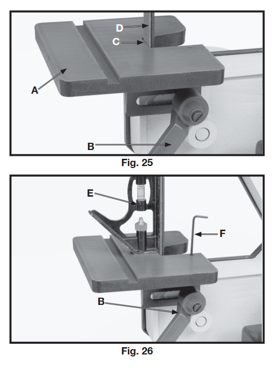 under the handle.
To avoid trapping the work or fingers between the table and sanding belt, the table
edge (C) fig. 25, should be positioned a maximum of 1/16
inch from sanding belt (D) as shown. For most sanding operations the table is set at a 90 degree angle to the sanding belt.
A positive stop is provided to insure fast positioning of the table at 90 degrees to the belt. Loosen the table lock lever (B) Fig. 26, and tilt the table to the rear as far as possible.
Using a combination square (E), place one end of the square on the table with the other end against the sanding belt, as shown, and check to see if the table is 90 degrees to the belt. If the table is not at 90 degrees to the belt, turn adjusting screw with wrench (F).
The adjusting screw should bottom against the frame when the table is 90 degrees to the belt. The table can be tilted 45 degrees to the front, as shown in Fig. 27, by loosening lock lever (B). Use a combination square (E) check to set the table at 45 degrees to the belt and tighten lock lever (B).
To avoid trapping the work or fingers between the table and sanding belt, the table edge (C) should be positioned a maximum of 1/16 inch from sanding belt (D) when the table is tilted
DISC TABLE ADJUSTMENTS 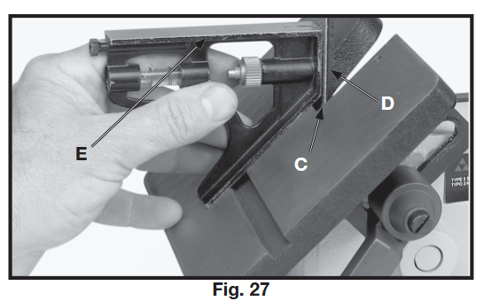
The disc table (A) Fig. 28, can be tilted 45 degrees up or down, by loosening lock handle (B), tilting the table, and tightening lock handle (B).
NOTE: The lock handle (B) is spring-loaded and can be repositioned by pulling out the handle (B) and repositioning it on the serrated locking stud located directly underneath the handle.
To avoid trapping the work or fingers between the table and sanding disc, the sanding disc (C) should be adjusted so it is a maximum of 1/16 inch from edge of table (D). This can be accomplished by moving the sanding disc in or out on the motor shaft.
To check and see if the table is at 90 degrees to the sanding disc, place a square (E) 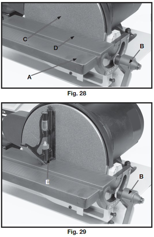
Fig. 29, on the table with one end of the square against the sanding disc, as shown.
If an adjustment is necessary, loosen lock lever (B), move table
until you are certain it is at 90 degrees to the sanding disc and tighten lock lever (B).
Then loosen screw (F) Fig. 30, and adjust pointer (g)
so it points to the “0” degree mark on the table scale.
REMOVING AND INSTALLING ABRASIVE BELTS 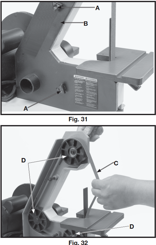
1. Disconnect machine from power source.
2. Remove the two knobs (A) Fig. 31, and remove the side cover (B) from the belt unit.
3. Press down on the tracking knob to release belt tension and remove belt (C) Fig. 32,
from the three pulleys (D), as shown.
4. Install new 1″ x 42″ belt and replace side cover. Check belt tracking by referring to the section “TRACKING THE SANDING BELT,” and adjust if necessary.
IMPORTANT: Some belts have a directional arrow printed on the inside of the belt. In these cases the belt must be installed so the directional arrow points in the same direction that the belt is moving. The sanding belt travels down at the front of the machine.
REMOVING AND INSTALLING ABRASIVE DISCS
1. Disconnect machine from power source.
2. Remove the sanding disc table.
3. Remove the old abrasive disc by peeling it from the sanding disc plate.
4. Clean the disc plate thoroughly.
5. Remove the backing from the new abrasive disc and press the abrasive disc firmly onto the disc plate.
6. Replace the sanding disc table.
MITER GAGE 
A miter gage (A) Fig. 33, is supplied with your sander and can be used on the disc table, as shown, or on the belt table.
The miter gage can be set up to 45 degrees right or left by loosening lock knob (B), tilting miter gage body (C) to the desired angle and tightening lock knob (B).
Shutdown & Cleanup
Do not use highly volatile solvents such as gasoline, naphtha, acetone or lacquer thinner for cleaning your machine.
KEEP MACHINE CLEAN Periodically blow out all air passages with dry compressed air. All plastic parts should be cleaned with a soft damp cloth.
NEVER use solvents to clean plastic parts. They could possibly dissolve or otherwise damage the material.
LUBRICATION & RUST PROTECTION
Apply household floor paste wax to the machine table, extension table or other work surface weekly. Or use a commercially available protective product designed for this purpose. Follow the manufacturer’s instructions for use and safety.
To clean cast iron tables of rust, you will need the following materials: a sheet of medium Scotch-Brite™ Blending Hand Pad, a can of WD-40® and a can of degreaser. Apply the WD-40 and polish the table surface with the Scotch-Brite pad. Degrease the table, then apply the protective product as described above.
Materials
This machine is for finishing/deburring metals only, please DO NOT use this machine for woods/plastics/etc DO NOT SAND MAGNESIUM THIS CAN CAUSE A FIRE
Files & Resources
User Manual can be found Here
Specifications
| Name | Delta Sander |
| Manufacturer | Delta |
| Year Released | 2004 |
| Model | SA180 |
| Serial No. | 019708F2004 |
| Belt Size | 1″ X 42″ |
| Disc Size | 8″ Adhesive Backed |
| Dust Chute Size | 1-1/4″ ID |